DEEP-SEA QUAY WALL FOR OFFSHORE WIND ENERGY TERMINAL ON MAASVLAKTE 2 ROTTERDAM – NL
Author: Patrick van der Schaaf Bsc Eng.
Manager Business Development Woltman Piling & Drilling Rigs Dieseko Group
Sliedrecht The Netherlands
Phone +31 184 430900
Email p.vd.schaaf@woltmanrigs.com
ABSTRACT
During 2016 foundation piling works were completed to allow for the construction of a production and storage/handling terminal in Rotterdam. It is there that steel foundations will be produced for offshore wind farms and the oil and gas industry. Several Dutch contracting companies were involved in constructing: foundations for an assembly hall a barge quay and a deep-sea quay wall. For the hall foundations cast in situ concrete vibro piles were created. Open ended steel casing piles were also installed due to very high cone resistances which made it impossible to perform cast in situ piles in certain areas. The quay wall was constructed with open ended steel casing piles in combination with sheet piles. A deep-sea quay wall was also constructed to provide enough storage area for the offshore mono piles. This project was unique and challenging due to the use of different foundation technologies in challenging circumstances and soil conditions. This paper will give an insight into the Dutch use of varying foundation piling techniques for deep-sea quay wall constructions. It can be concluded that even experienced local contractors can be surprised by variations in soil conditions. It will also show how the contractors adapted to the difficult circumstances.
PROJECT OUTLINE
The project consisted of a barge quay near the assembly hall with a length of 500 metres width of 42 metres and a height of 35 metres and a
deep-sea quay wall 480 metres in length. This paper concentrates on the foundation works for the construction of the deep-sea quay wall. The construction of the deep-sea quay wall consisted of a combination of open ended steel casing piles with a diameter of Ø 1420 mm and a wall thickness varying between 21 and 23 mm. The lengths of the steel casing piles varied between 32 and 37 metres. Between the steel casing piles triple PU 28 sheet piles were installed with lengths varying between 26 and 29 metres. In the Netherlands a combination of open ended steel piles and sheet piles is known as a “combi wall”. For the deep-sea quay wall a steel combi wall was shored with steel H- section profiles that were driven in a raked position whilst being injected with grout so called MV-piles. The MV piles for this project consisted of steel HEB 600 sections with lengths from 52 up to 59 metres and were installed with angles varying between 42.5 and 47.5 degrees. For a detailed overview regarding the project specifications reference is made to table 1 which is presented below.
Table 1. Project specifications for the deep sea quay SIF terminal
Description Number Dimensions Lengths Steel quality
[pcs] [mm] [m1]
Open ended steel casing pile 145 Ø 1420 x 21/23 32 – 37 X70
Steel triple sheet pile 145 3 x PU 28 26 – 29 S355GP
MV piles 113 HEB 600 52 – 59 S355J2N
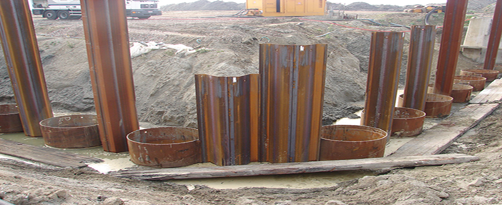
Fig 1. Configuration combi wall
PROJECT APPROACH
The new SIF terminal will be located on a new harbour area in Rotterdam – Maasvlakte II which consists of reclaimed land. In 2008 land reclaimation works over an area of 20 km2 near Rotterdam started to create a new harbour area located in the North Sea near the already existing harbour area of Maasvlakte I. From this 20 km2 of new land Maasvlakte II uses almost 10 km2 for sea protection structures and infrastructure such as roads railways harbours and harbour quays. The remaining 10 km2 is available for commercial use such as the chemical industry distribution and container terminals. The new harbour area of Maasvlakte II was designed with a depth of 20 metres specifically for large container ships. This makes it more accessible than the surrounding harbours in Belgium and Germany which have limited depths.
It was its depth of 20 metres that created the challenges in constructing this new wind energy terminal with its deep-sea quay wall. Ordinarily to construct combi walls it is common to first drive open ended steel casing piles. After the steel casing piles have been installed sheet piles are driven between the steel casing piles where the clutches of the open ended piles and sheet piles interlock each other. The common working method for deep-sea quay combi walls in the Netherlands is to first drive the open ended steel casing piles with a vibratory hammer until refusal. The remaining part of the open ended steel casing piles can then be driven by a diesel or hydraulic impact hammer. For this project the open ended steel casing piles Ø 1420 mm were driven with a PVE 110 M vibro hammer which has a maximum centrifugal force of 2198 kN and a maximum frequency of 1350 rpm. The piles were driven to a depth of approximately 24 metres with a vibratory hammer. The remaining part of the piles were driven with a Delmag D-160 diesel hammer.
Drive-ability assessment

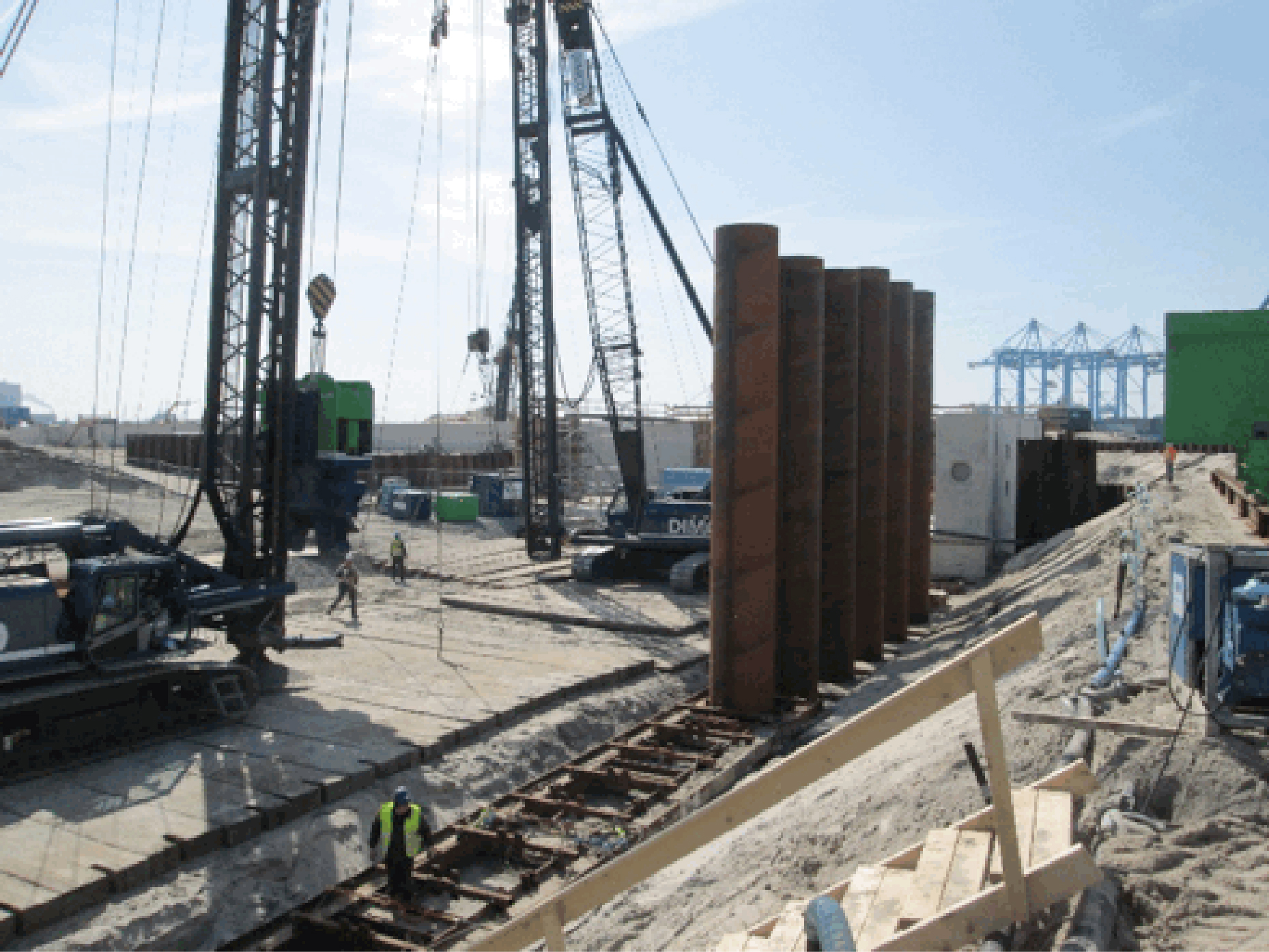
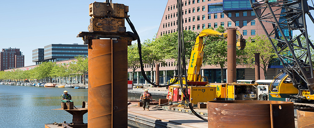
Fig 2. Installing of open ended steel casings in progress
A smaller PVE 2350 VM vibratory hammer was used to drive the triple connected PU28 sheet piles to the required depth between the open ended steel casings. Previous project experience at the Maasvlakte I area nearby indentified that waterjetting could support the drive-ability of sheet piles. However due to the high pore water pressures in the new reclaimed soil layers at the Maasvlakte II project waterjetting did not provide satisfactory results. For this reason it was decided to perform pre-drilling to a depth of 15 metres in order to support the drive-ability of the PU28 sheet piles. Together with pre-drilling of the sheet pile locations bentonite was poured into the boreholes to reduce the soil friction on the sheet piles and to the support the drive-ability.
DRIVE-ABILITY PREDICTION
Before the start of the piling operations the piling contractor requested that the Dieseko Group performed a drive-ability assessment of the open ended steel casing piles Ø 1420 x 23 mm with a length of 37 metres. For this assessment the ICE-vibro geodrive prediction program was used. With this computer program drive-ability predictions can be made based on the (sheet)pile specifications pile lengths and soil profile. based on a representative cone penetration test graph known as CPT graph the drive-ability program predicted that with a PVE 110 M vibrohammer the open ended steel casing could be driven to a maximum depth of approximately 24 metres below working level.

Fig 3. CPT graph
The CPT graphs shows the presence of dense sand layers from NAP +50 to NAP 0.0 metres. NAP is the abreviation for Normaal Amsterdam Peil (translated: Normal Amsterdam Level) which is the reference level for height survey levels in the Netherlands. The piling operations for the SIF terminal were performed from a working level of NAP -1.5 metres. based on the drive-ability prediction that the open ended steel casing piles could be driven to a level of NAP -1.5 minus 24 metres = NAP -25.5 m. This level is marked with the red arrow in the graph. The following figure shows the results of the drive-ability prediction.

Fig 4. Results drive-ability prediction open ended steel piles Ø 1420 mm
The dotted line in figure 4 indicates the soil resistance at the toe of the casing pile whilst being driven. The second line indicates the remaining driving force at the toe of the pile. The level where both lines cross can be considered as the maximum level for the vibratory hammer to reach with sufficient penetration speed. Below the cross point of the lines at a level of -24 metres equal to NAP – 25.5 m the penetration speed will drop to a level where this can be considered as refusal. In other words from this point the vibratory hammer can be switched with a diesel- or impact hammer to continue pile driving to the required pile toe depths in this case to a level between NAP -34.0 and -39.0 metres.
PILING OPERATIONS DEEP-SEA QUAY WALL
The piling contractor followed a specific work method for installing the open ended steel casing piles and the sheet piles. Working with the drive-ability prediction the piling contractor decided to drive the open ended steel casing piles with a Woltman 160 PR piling rig fitted with a leader guided PVE 110M vibratory hammer up to a depth of 24 metres below working level. With this set-up the first row of open ended steel casing piles was pre-driven into the soil. Another piling rig a Woltman 1000 PDS equipped with a leader guided diesel hammer Delmag D-160 drove the open ended steel casing piles to the required pile tip level. As a quality check blow counts of the Delmag D-160 diesel hammer were registered during the driving operations. In general at pile toe finish level the blow count over the final 25 cm ranged between 34 and 40 blows. This in relation to CPT values increasing 50 MPa of cone resistance over more than 10 metres depth.

Fig 5. Example of monitoring information during driving open ended steel casing piles
MONITORING
Due to high quality standards on the project the vibrations from the driving of the open ended steel casing piles with the PVE 110 M vibratory hammer were monitored by electronic registration equipment. The vibrations for driving the sheet piles were also monitored. Figure 5 shows information about the registered driving time frequency of the vibratory hammer amplitude acceleration and centrifugal force for the open ended steel casing piles. Each casing pile and sheet pile was monitored during the operation of piling works. A comparison between the drive-ability prediction and the monitoring results of the open ended steel casing piles is presented in table 2.
Table 2. Comparison drive-ability prediction with monitoring results
Drive-ability prediction Monitoring results
SRV toe = 500 – 1000 [kN]* 600 - 2000 [kN]
Max. frequency 1350 rpm** 20- 25 Hz = 1200 – 1500 rpm
Max. amplitude 115 mm*** 6 – 7 mm
Remarks to table 2
* The maximum value of SRV toe is based on the level where refusal is expected
** Max. frequency according the specification sheet of a PVE 110 M vibratory hammer
*** Max. amplitude is the mathematical amplitude of the vertical deflection. Suppliers of vibratory hammers refer to the double value of the
amplitude which is 229 mm for a PVE 110 M
SUMMARY AND CONCLUSIONS
Despite the piling contractor having prior experience working in the harbour area of Rotterdam the drive-ability of the open ended steel casing piles was predicted before the start of the piling operations. The drive-ability prediction showed that a PVE 110 M vibratory hammer could be expected to drive the open ended steel piles to a depth of approximately 24 metres. After reaching that particular depth they were advised to drive the casing piles to the required depth by a diesel- or impact hammer. During pile driving with a vibratory hammer the performance was monitored by an electronic measuring system. With this system it was possible to read the driving time frequency driving force and amplitude. When the drive-ability prediction was compared with the monitoring results it showed that the prediction was quite reliable. The open ended steel casing piles were driven with a vibratory hammer to a depth of approximately 24 metres below working level. The type of vibratory hammer suggested - a PVE 110 M was sucessful in driving the piles to the predicted level. To ensure an efficient piling operations the piling contractor switched to piling rigs and drove the remaining part of the open ended steel casing piles with a Delmag D-160 diesel hammer. The blow counts at the pile toe levels varied between 34 and 40 blows per 25 cm indicating that the diesel hammer had sufficient energy for this purpose and therefore was suitable for the job. For driving the PU28 sheet piles no drive-ability prediction was performed prior to the piling works. based on local experience the piling contractor decided to use a PVE 2350 VM vibratory hammer for driving the sheet piles combined with pre-drilling in combination with bentonite filling. Although waterjetting is a common solution in that particular harbour area it turned out that for this project this method was unsuccesful due to the recent land reclamation works causing high pore water pressures. Nevertheless the piling contractor was able to adapt to the challenging circumstances and executed the piling works in a succesful and efficient way. However for future projects it may be advantageous to also predict the drive-ability of the sheet piles. Monitoring results can also give valuable information about the piling works.

 Search terms: Product Name, Type, Application.


|
Rent Piling Equipment |
 |
Virtual Visit To Our Factory |
 |
Order Spare Parts |
 |